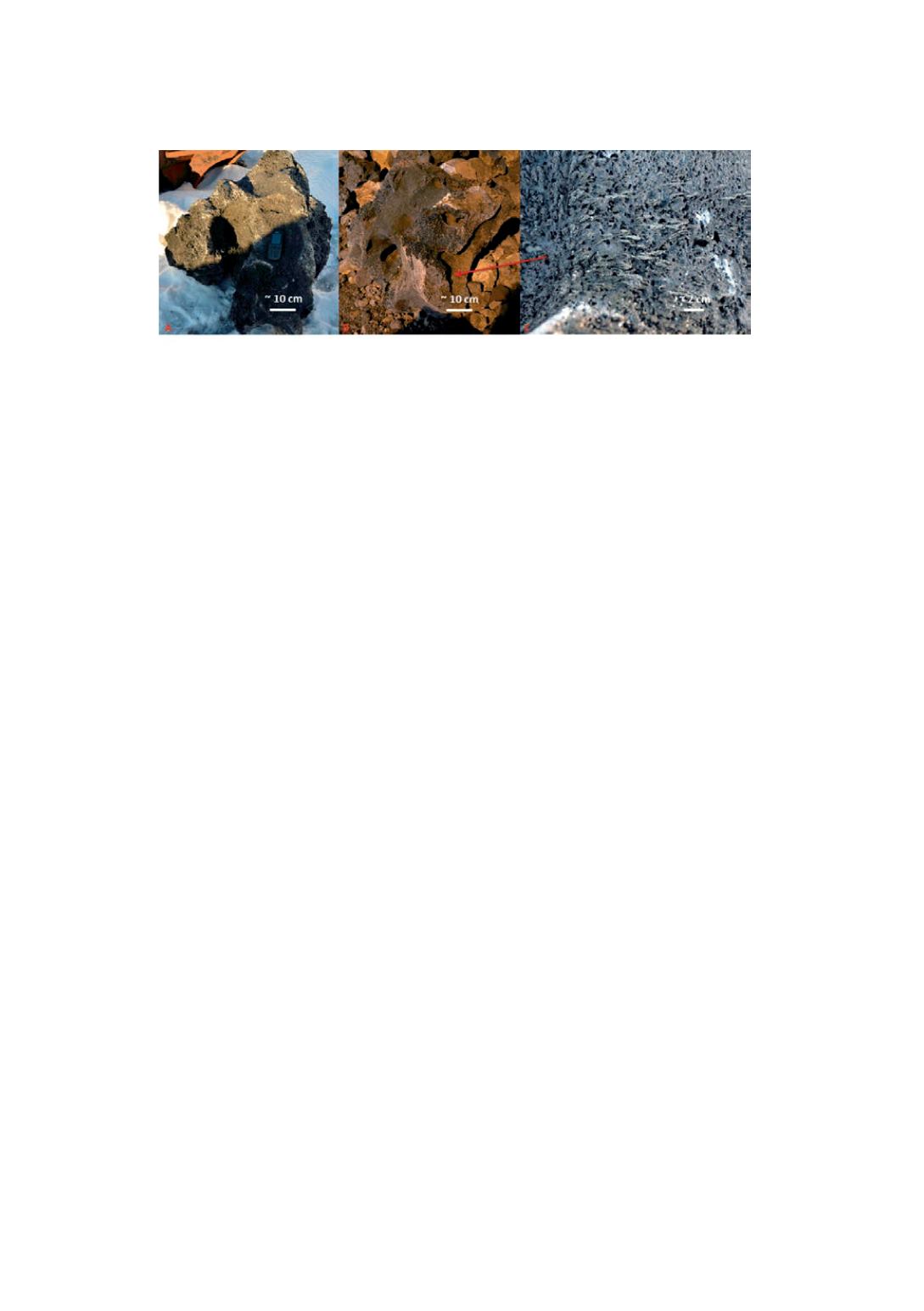

Figure 13:
SiC deposit with gas channels (A, B), SiC crystals on the channel wall (C). [3]
During the excavation of furnace no. 1 at Wacker it was possible to have close look
and pick up the sample directly from area around the electrode tip. Electrodes were
still in their working positions; they were not cut off before start of excavation, as it
was in case of other Si furnaces. Around the electrode tip there was area filled with
the mixture of SiC, Si and melted quartz. It is believed that the production of silicon
in this zone is to be preliminary, thus it was marked on the figure 9a as Si production
zone. Additionally on the figure 9a, below electrode the cavity was marked. It is
believed that it was filled with melted materials from Si production zone, as furnace
was stopped. It is expected that in this area the electric arc will go towards Si bath or
the SiC crust. Similar cavity was observed during the excavation in Elkem
Thamshavn, however there was only SiC crust surrounding the electrode tip. Below
the electrode small region with metal bath was identified, however the major zone in
the bottom was mixture of green slag and SiC.
Some very small areas of metal bath was observed in Wacker furnace no. 1 below
electrodes. However, the main phase was mixture of SiC and Si, which was about 2m
thick. In case of furnace no. 4 the liquid metal leaked out during the dig out, thus was
very difficult to estimate area where it was cumulated.
Conclusion
•
Five industrial scale furnaces (two FeSi and three Si) were excavated for the
purpose of finding reaction zones.
•
Excavation of two FeSi furnaces indicate that during 50FeSi production process
heat to the system is delivered via coke bed. While 75FeSi production process
seems to be cavity operation as Si production process.
•
Inactive zone, consisting mostly of thick slag layer seems to be significant zone
in the furnace. Thus, it limits the space for "active" zones, for example hinder
the flow of the charge material but also can cause the problems with the
tapping a furnace.
•
Distribution of the zones, and appearance of different zones it self can firstly be
determined by furnace operation strategy, not by used raw materials. Wacker
furnaces used similar raw materials-however, zones and they distributions in
those furnaces differ significantly.
Acknowledgement
The authors wish to thank the staff in Finfjord, Elkem Bjølvefosen, Elkem
Thamshavn and Wacker Holla for great support and hospitality during the excavation.
41


