


 180 / 390

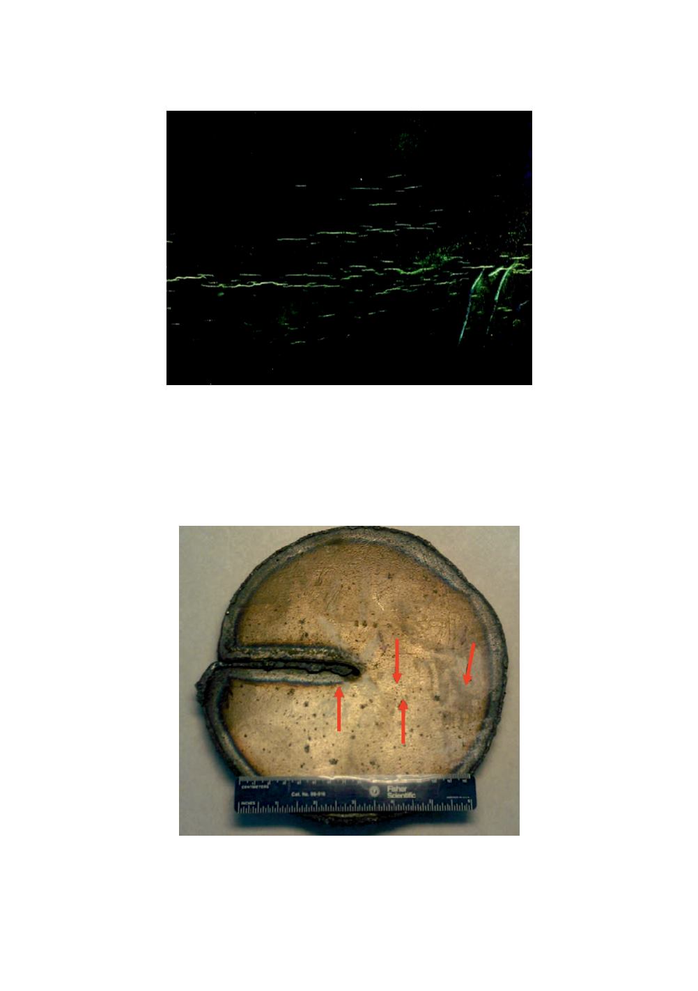
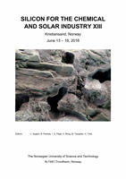
Figure 1:
Wet fluorescent magnetic particle image of the cracks inside the reactor.
Even after identifying the cracks with WFMP, most of them were not possible to
visually locate under normal light. To further characterise the cracks, two pieces 150-
200 mm diameter were identified and cut from the reactor wall. Arrows in Figure 2
indicate the position of some of the cracks that were only possible to identify with
WFMP.
Figure 2:
Inside surface of a cut-out. The red arrows indicate the location of cracks identified
by visual examination at 10x–20x magnification.
172