


 184 / 390

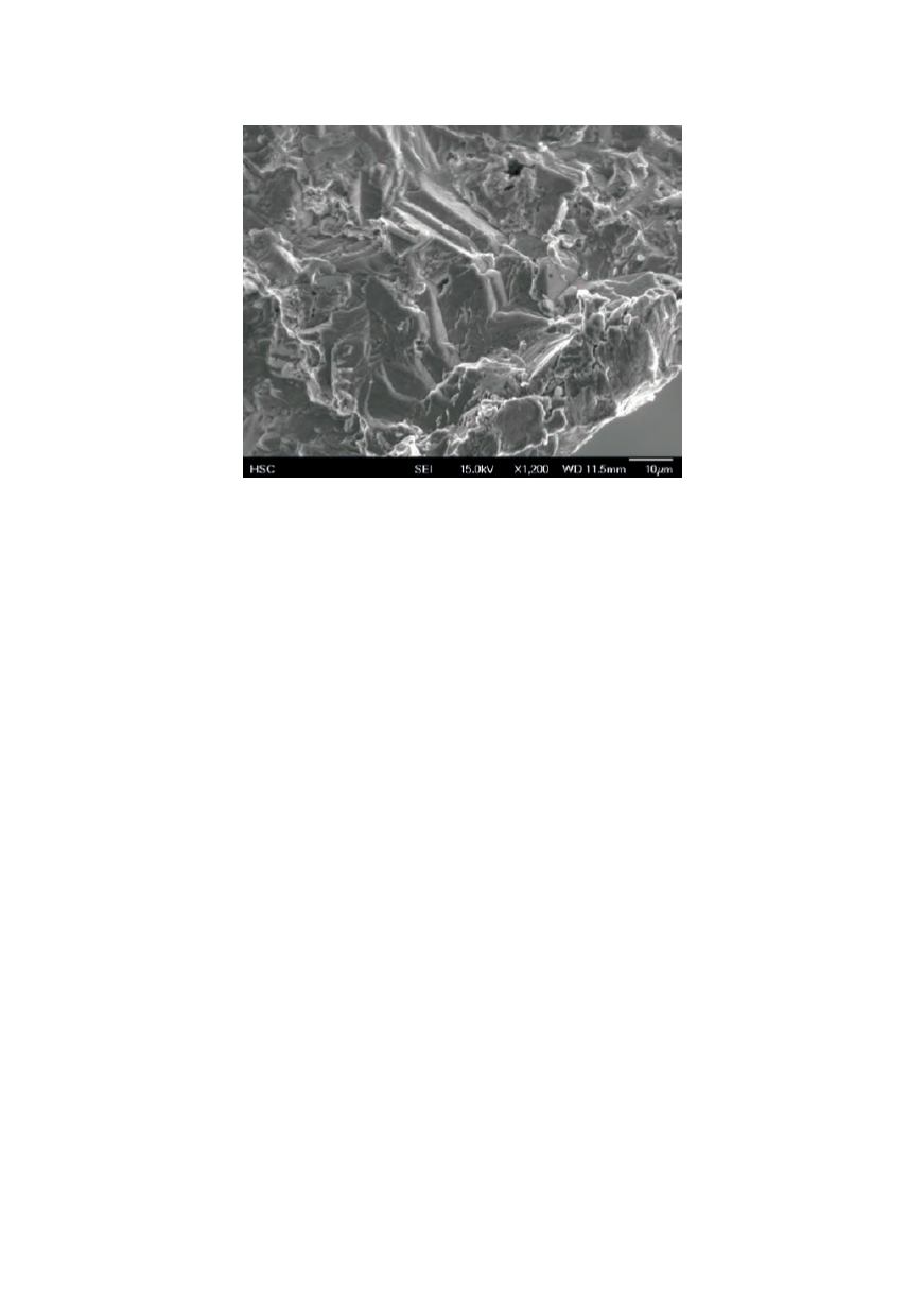
Figure 9:
Electron micrograph of fracture surface.
The depth of the cracks investigated was from 5 to 11 mm deep, which is consistent
with the expected rate of crack formation for SCC of 1 – 3 mm/year (1). As shown in
Figure 4 to Figure 9, the cracks all share several features:
x
The apparently simultaneous initiation and propagation of multiple cracks at a
given location.
x
Crack propagation with the development of extensive branching.
x
The presence of corrosion products in the crack indicating a chloride salt.
x
A trans-granular cleavage-type fracture surface morphology.
x
Cracks only located in some areas of high internal stress due to forming or
welding
While individually none of these uniquely identify a specific failure mechanism, taken
together they are consistent with stress corrosion cracking as the damage mechanism
or failure mode.
Root Cause
Stress corrosion cracking requires the simultaneous presence of three factors: a
susceptible material (in this case carbon steel), a specific corrosive environment or
agent, and a tensile stress above a certain threshold. Generally, three basic
mechanisms have been identified for stress corrosion cracking (1).
1. Active path dissolution, where the bulk of the material is passive, but
segregation of impurities at the grain boundary results in a susceptible
material. This process can occur in the absence of stress.
2. Hydrogen embrittlement, which occurs where hydrogen is drawn to areas of
stress in the matrix, generally at the grain boundary. In general the reactor
temperature is too low for this mechanism.
3. Film induced cleavage, when a normally ductile material becomes coated with
a brittle film formed by a corrosion process. The ductile surface blunts the
crack, where the brittle film is reformed, progressively expanding to form a
trans-granular fracture.
176