


 96 / 128

90
THE COLUMNS
The columns are an important aspect of the project in so far
that they give an animal like character to the wood structure;
giving them legs. But there is one big difference between legs
and columns: the legs are supposed to walk, while the columns
stand fixed. In many aspects our choice has been to visually and
structurally keep them as columns. In fixed position the best
balancing number is 3, they can be straight without any “knee”
joints and steel columns allows for equally slim structures,
even though more weight lies on some of the columns. Another
important difference is that the columns should be fixed in the
ground.
On the other hand, there are several structural solutions that
emphasize the resemblance with animal legs. Even though
a column should be fixed, it constructively wears “shoes”
to attach them to a foundation, and in our case we found it
important to accentuate this detail (fig. 18). Since the columns
only need to be fixed in the object, not in the foundation,
the joint detail on the ground is unfixed, making a dynamic
expression. However, in the transition from column to wood,
the joint is fixed by preparing a compartment of steel placed
in between the CLT sections (fig. 18). This detail is done at the
workshop before the assembly of the CLT sections. At site then,
the columns are attached to these compartments.
THE GROUND
The creation of an extra-terrestrial space is needed to host our
guests. Based on a crater morphology, the new area is built
using superficial ground movements in which the compensation
between excavations and slopes avoid waste soil.
As a delimitation for the functions and areas we use different
materials: sand, gravel, vegetation and stone. These materials
create an intinerary for the visitors as well as permit the
evacuation of rainwater, which would be absorbed by the
undisturbed soil.
350cm
80cm
60cm
450cm
130cm
1
2
5
6
7
1
2
5
8
10
11
12
13
15
14
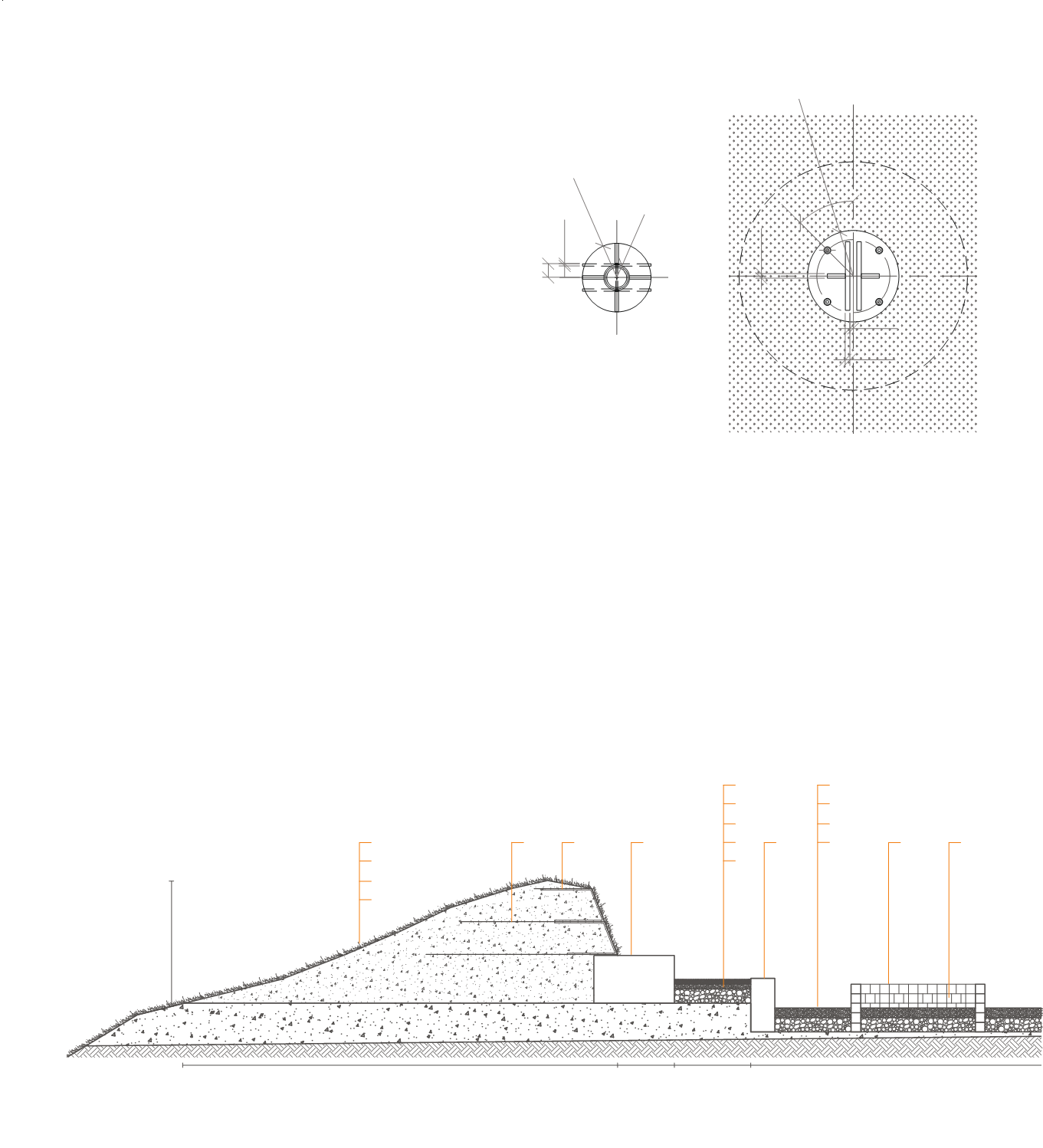
GROUND
1.Undisturbed soil
2.Permeable slope soil
3.Reinforce fill with plantable fill
4.Native vegetation cover
5.Compacted agregate 15cm
6.Gravel 5cm
7.Sand 5cm
8.Gravel 10cm
9.Slate unit paver 5cm
10.Geogrid 8x8mm Ø2mm
11.Turf reinforcement mat
12.Concrete blocks 50x85x50cm
13.Concrete blocks 25x50x50cm
14.Concrete blocks 10x10x10cm
15.Air gaps 5x10cm
16.Concrete blocks 10x30x10cm
1
2
3
4
Fig 17: Ground section 1:50
405
605
150
100
R150
R200
45°
R160
60
10
R56
20
20
15
15
405
605
150
100
R150
R200
45°
R160
60
10
R56
20
20
15
15
Fig 16: Columns horizontal section
COLUMNS
1.Fixing in the wood: welded steel plates
and tube Ø112mm, thickness 6mm.
Bolts Ø8mm
2.Column: steel tube Ø100mm, thickness
6mm
3.Welded steel plates base, pin
connection, bolt Ø12mm
4.Anchor bolts 12 mm
5.Steel reinforced concrete foundation
6.XPS insulation
7.Gravel
60
20
15
R150
R
45°
R160
60
10
R56
20
20
15