


 95 / 128

89
WOOD WORKS
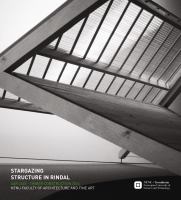
The primary structure is a double curved piece of carved
wood. With an uneven shape standing on columns placed quite
far underneath the “body”, the structure is behaving like a
cantilevered beam (fig. 14). This challenges the wood, which
should take up the forces only in its fibre direction. Our solution
is CLT (cross laminated timber) in vertical sections, connected
together with wood dowels (fig. 12.3). The tension forces across
the sections in the upper area, underneath, and on the sides
overhanging the columns, are taken up by steel wires (fig. 12.2).
The production of the primary structure starts with the
3D-model of the complete form. The form is divided in vertical
sections, ending up with 43 unique sections constituting the
whole (fig.12.1). The width are based on a CLT standard; 120mm
with 5 layers. To exploit the blocks of CLT, each section should
consist of two parts, connected later with wooden dowels. To
prevent this split to weaken the structure, it should be located
on different spots on the different sections. The following
process is a job for the specialist; to generate data for a CNC
machine to cut the exact double curved form. Amongst others,
the workshop Snekkeriet in Verdal has this expertise.
An important aspect of CLT is its fragility towards water. Its
exposed fibers absorb water, causing quick damage when
untreated. On the outside the protection will be in the cladding
details, but on the inside it is important to keep the wood
exposed. A solution is to wax the surface (normal technique at
Snekkeriet) to prevent both water and dirt from destroying the
wood.
ASSEMBLY
The assembly should be done at the workshop, leaving a fixed
form ready to be transported (fig. 13). The crucial measures
are that of the Big sister: height 3,2m and width 4m. Maximum
height an width on the road to Rindal is 4,5m and 4,2m. The
width are accepted for transport of house modules, escorted by
the police.
At site the two objects are placed on the columns which have
already been attached to the foundation (see columns detail).
Foundations and columns will be placed according to UTM
coordinates from an exact site survey.
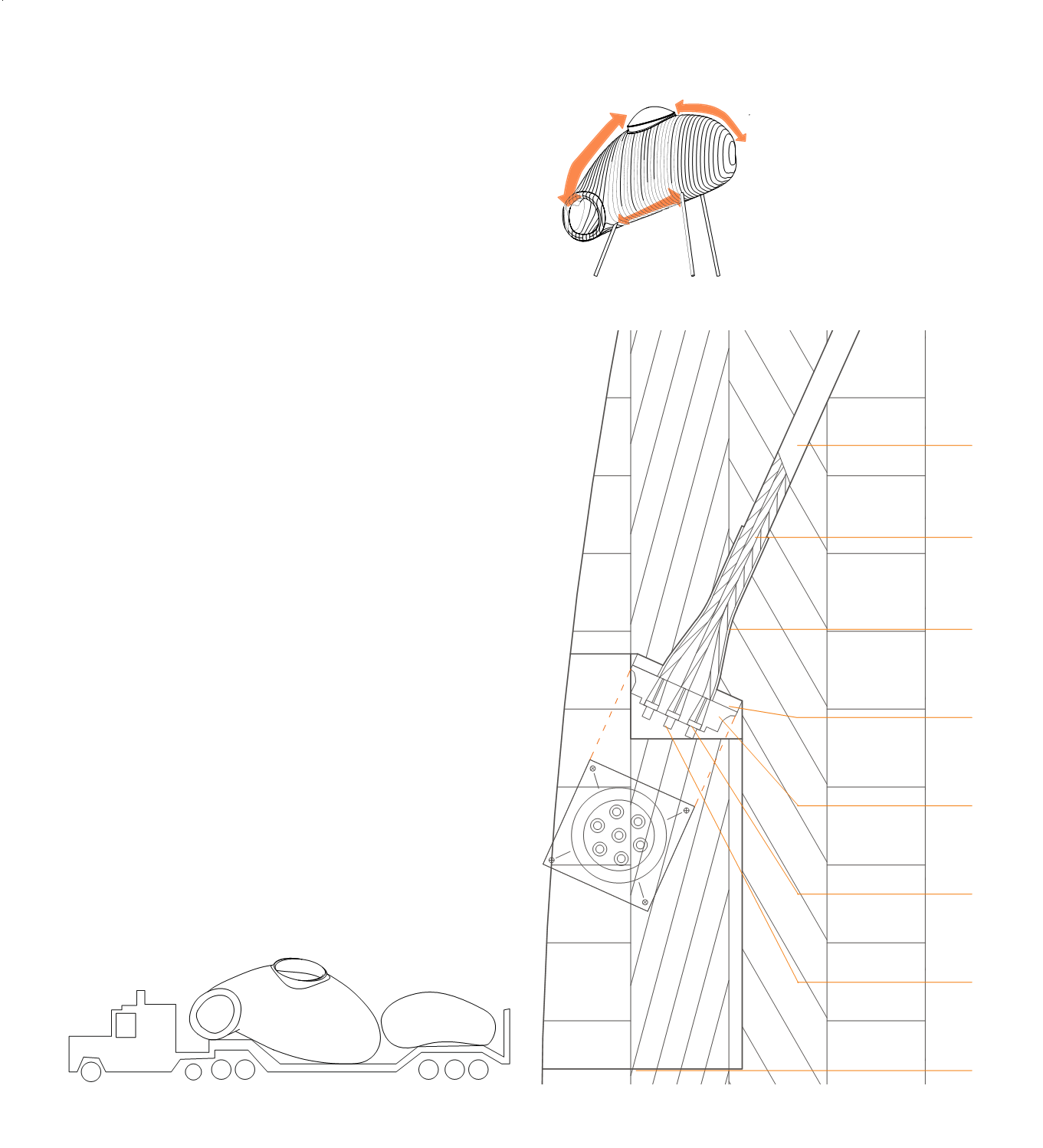
1
1.Plastic cover
2.Steel corrugated duct
Ø10mm 7Ø3mm
3.Trumpet
4.Steel plate 50x50x5mm
5.Wedge plate 50x50x13mm
6.Wedge Ø6mm
7.Grout cap
8.Wood cover
2
3
4
5
6
7
8
Fig 15: Ending steel wire detail 1:2
Fig 14: Tension forces scheme
Fig 13: Truck scheme