


 122 / 128

116
DETAILING TRUSS
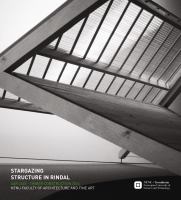
We chose to focus on four details within our main truss.
These details are calculated and optimally dimensioned
for their task. We make only use of only dry wooden joints
and pegs, steel plates or bolts are not used in the joinery
except for taking the pressure of the steel tension rod.
The joints are designed in such a way that they can easily
be made by hand or machined. The erection of each frame
is a relatively straightforward process. The joints all fit
together to form the basis of the frame. The dowel in joint
1 tightens the joints making it easier for the tension cable
to be secured. This creates a stable frame which can be
moved into place.
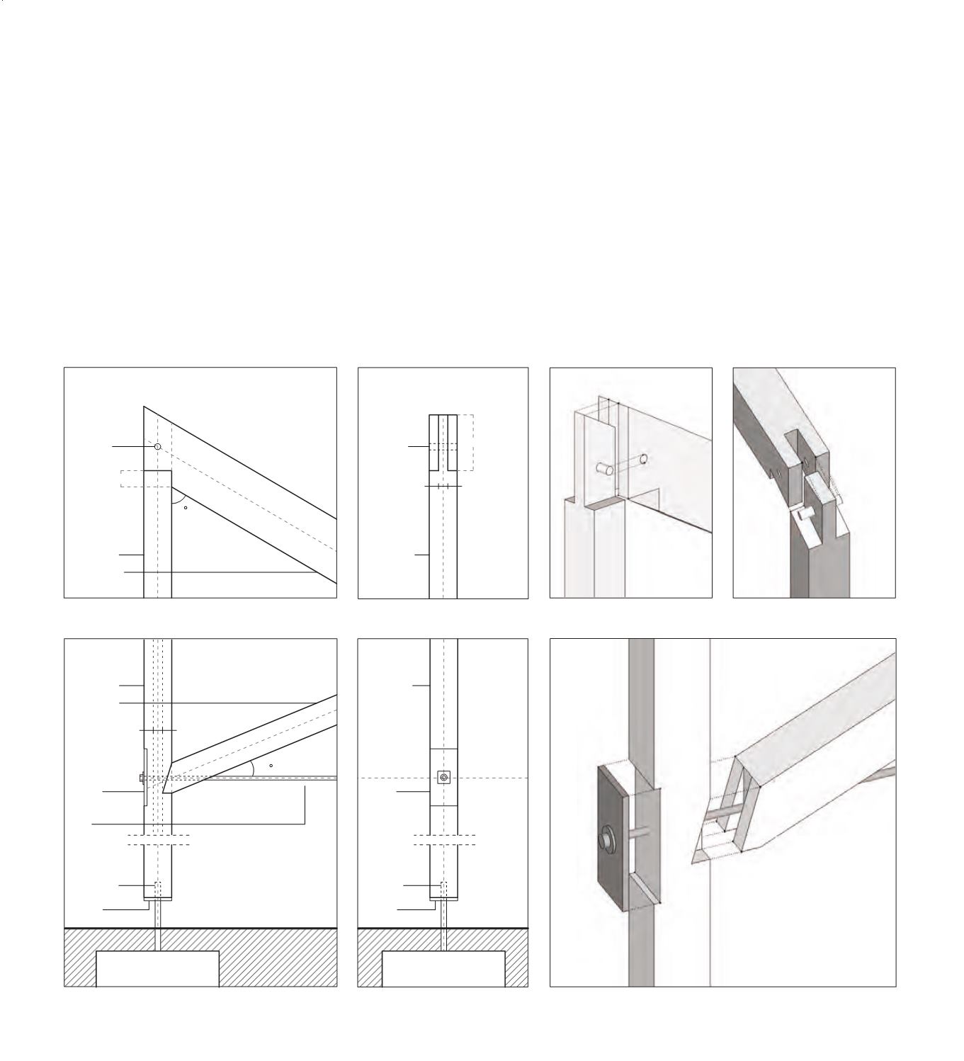
Bridle joint and foundation detail
2
This detail takes both compression and tension. The tension
is because of wind forces that can lift the roof when the wind
comes in via the entrance. The compression comes from the
facade and the main diagonal beams own weight. The tenon is
made to go all the way through the top beam so there is more
material that can take the tension to the dowel. The size to
strength ratio is strongest in this one third construction.
In this joint the tension rod is joined within the detail. Most
important was that the rod is going through the centre of the
joint to be able to properly put tension on the structure. A bolt
with a diameter of 21 mm through a steel plate embedded into
the 90x90 column ensures the tensioned structure.
1
2
Mortice and tenon joint
20 mm dovel
20 mm dovel
Pine 90x90 mm
180 mm
30 30 30
53 mm
30
Pine 90x90 mm
Pine 180x90 mm
1
Pine 90x90 mm
Pine 90x90 mm
Pine 90x90 mm
Steel plate
10x90x185 mm
Steel plate
10x90x185 mm
Steel plate
10x90x90 mm
Steel plate
10x90x90 mm
Steel wire
12 mm
Steel Ø 20 mm
Steel Ø 20 mm
30 30 30
22,5