


 46 / 116

46
PROCESS
planning
DESIGN TO PRODUCTION
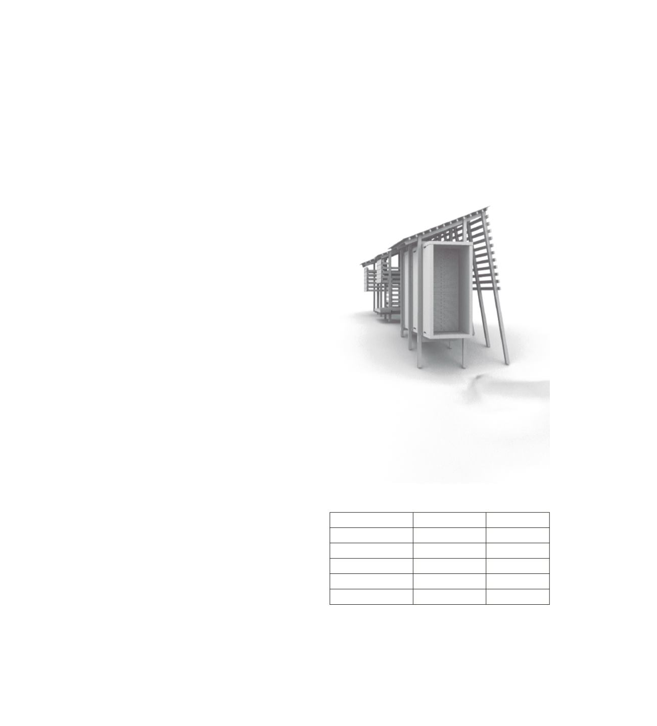
During the design process we kept constantly
working on a 3D model in Rhino. Thanks to one
common master file with a defined grid and origin
point, it was easy to adjust and redraw several parts
of the design at the same time by different student
expert groups.
Meanwhile one team started to develop a
Grasshopper script that translates the 3D design
into useful numbers for cutting lists needed in the
building period. The flexibility in the code gives the
possibility to change the design even in a late phase.
Because it is linked to the geometry, the script out-
come adjusts while the 3D model gets changed.
Therefore, the 3D model needs to be as accurate as
possible. Small incorrect details can affect the
outcome immensely and lead to mistakes in the
building process. So, using this technology should
be considered from the very beginning of the
design.
Although we had produced cutting lists for all the
timber work of the project, we ended up just using it
for several parts such as battens, light constructions,
crossbeams and a few special massive wood
elements that could not be cut after the assembly.
Furthermore, the lists were helpful concerning
material calculations.
CROSSBEAMS
POSITION LENGTH
0A - 0B
1482
2B - 2C
1334
3B - 5B
1329
4A - 4C
2733
6A - 7A
1638
▵ Example of a cut list. The frames were given names according to posistion
and to make it easier to place other parts.
▵ Rendering of the final model.