The current ROV was designed with simplicity in mind due to the designers having no previous design experience.

Therefore this could be a new mechatronics project.
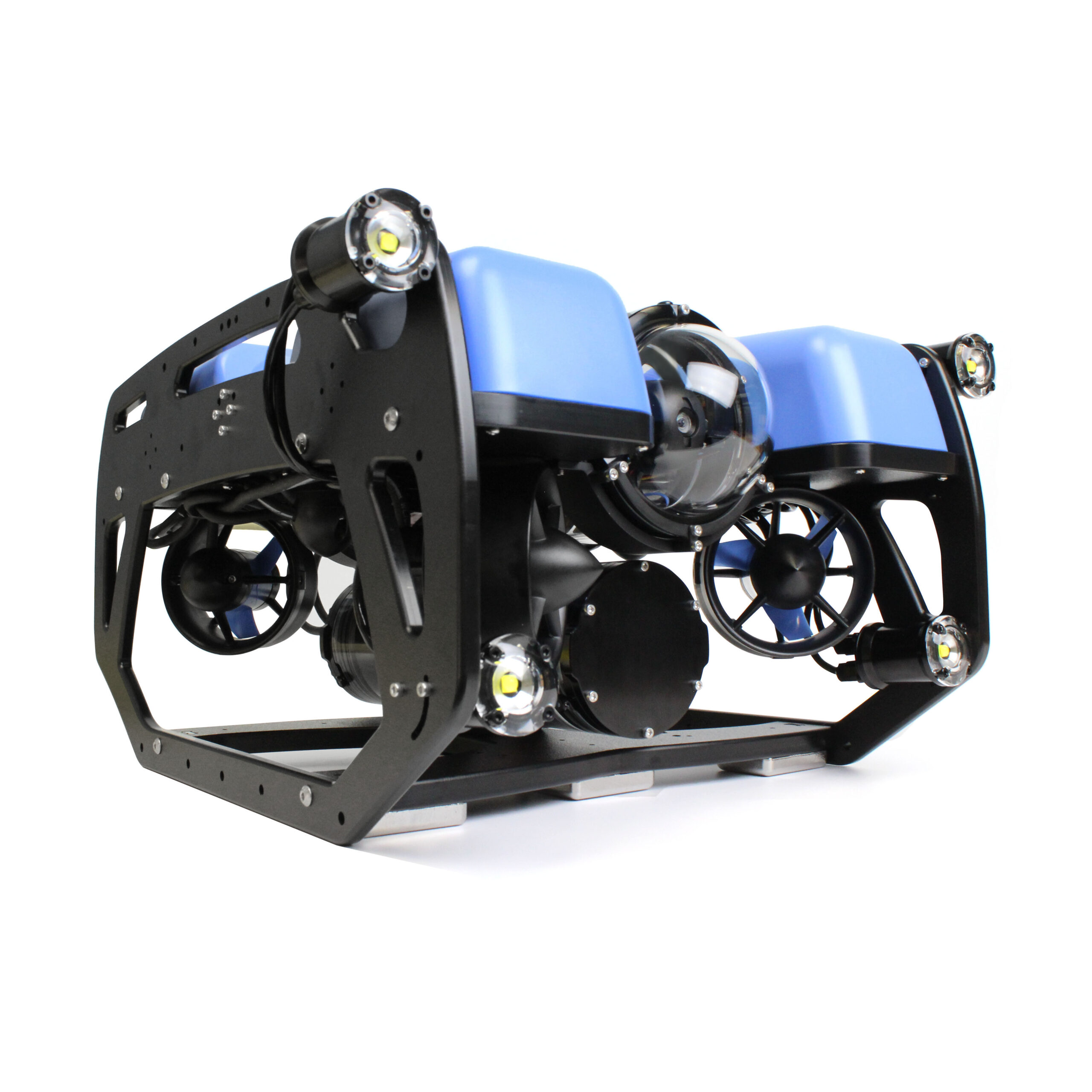
Blue robotics has designed a very potent ROV.
Suggestions for new rover.
- The current rov is not stable underwater. This can be solved by adding buoyancy on the top and weight on the bottom.
- For more effective movement, additional thrusters can be added.
- One aluminum chamber and one electronics chamber allows the current ROV electronics to be transferred to the new ROV.
- More robust bodywork
- Protection for thrusters?
- Fit inside the platform
- PS: The power converters need a heatsink
- Could be achieved by a aluminum chamber
Information from Bachelor's thesis in Automation may 2022 " Development of ROV for aquaculture inspection platform" by Tony Paulsen and Petter Henriksen.
Previous design and Manufacturing of ROV body
For the final design a circle shape was chosen due to it allowing easy mounting of thrusters. For the thruster positioning we decided to mount them at 120 degree intervals, this allows the ROV to move in all directions. This thruster placement was taken from an earlier ROV made by an- other group. The shape also gives a lot of surface area for mounting sensors, lights and other components. The circles are made out of acrylic, the material was chosen due to its light weight and high strength. Working with acrylic was made simple due to NTNUs laser cutter. The laser cutter allowed the group to make designs in Fusion 360 and then cut them out with high preci- sion and speed, making prototyping new mounts and parts a lot easier.

To hold the two circles together three aluminum extrusions were used, they are fastened with nuts and bolts. These extrusions are also used as mounting points for the thrusters. To hold the BlueRobotics 4 inch waterproof enclosure in place, a bracket made out of acrylic was designed in Fusion 360, see Figure 4.4. The bracket was cut out with the laser cutter and then glued in place with epoxy. The reason for not permanently mounting the enclosure in place was to make maintenance easier and allowing for reuse of the enclosure, seeing as the current design was made to be a prototype this was deemed optimal.

Due to the small amount space in the enclosure and the quantity of components, custom hardware mounts were needed to be able to fit everything inside. It is also important to keep EMI emitting components away from sensitive components, as the RPi. To make these, Fusion 360 was used for designing, and then they were produced with the schools Ultimaker2+ 3D printers, see Figure 4.5.

External box (Was broken at last test)
When working on putting everything together it quickly became apparent that space inside the enclosure would be a issue. It was quickly decided that adding an external box to house components that produce electrical noise and heat would be a good solution. The box is IP66 rated and is filled with clear casting epoxy so that it does not buckle under the pressure at the depths the ROV will operate in.
A new external box has since been made.