Ultrasonic cement evaluation in oil and gas wells
The task of evaluating cement jobs conducted in oil and gas wells is important e.g. to guarantee the safety during production and that no oil or gas is leaking to the surroundings. One method used for this evaluation is the ultrasonic pitch-catch technique, which involves excitation of Lamb waves in the steel pipes (casings) placed in the well. To better understand the physics behind the ultrasonic logging techniques being used, a set of measurements has been conducted on a desktop laboratory. A small selection of the results is presented here.
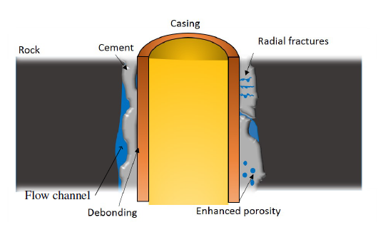
At an oil or gas field, petroleum oil and natural gas are produced by bringing the hydrocarbons to the surface through wells bored into the Earth’s crust. To ensure an efficient production of hydrocarbons and that safety requirements are met, several steel pipes are placed in the well followed by a cementing job, where cement is placed in the gap between the casing and the borehole wall, called the annulus. The cement placed in the annulus has to fulfil various criteria such as providing mechanical support to the well and, most importantly, preventing uncontrolled flow of hydrocarbons from the reservoirs to the surroundings. Since placing a proper cement sheath in a well is a difficult task, different problems can occur. These problems include debonding – where the cement and casing are not in perfect contact, and the creation of flow channels, as illustrated in figure 1.
To ensure that a cement sheath has been successfully placed, the cement has to be inspected through, for example, the use of ultrasonic tools. These tools are based on two techniques, namely the pulse-echo technique and the pitch-catch technique. In the latter technique, an ultrasonic transducer (transmitter) emits a short pulse towards the casing, exciting waves which starts to propagate along the pipe. These waves are so called elastic Lamb waves. As these waves propagate along the pipe, energy in the shape of pressure waves are generated at the boundary between the pipe and the surrounding media. By using a second transducer (receiver) to detect this pressure wave, the signal can be analysed to get information e.g. about the state of the cement sheath placed outside the pipe in an oil or gas well.
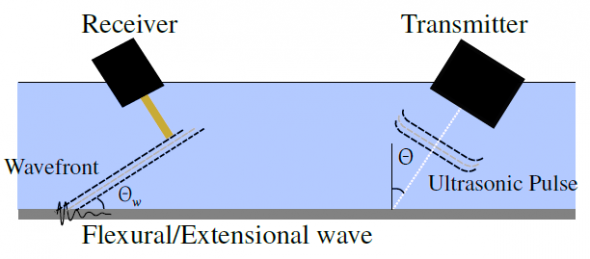
To study the behaviour of the Lamb waves being excited in the pipe, a set of experiments were conducted on the desktop laboratory setup at SINTEF Petroleum Research in Trondheim, called the Behind Casing Logging Setup (BeCaLoS, see figure 3). The setup is built as a plane layered structure with diameter of 50 cm. The top layer is a fluid layer and represents the inside of the pipe where one can position ultrasonic transducers in a flexible manner. To model the well, the deeper layer will typically be steel plates representing a first casing, a solid or fluid layer representing the material in the first annulus, etc. This setup serves as a suitable model of a well as the ultrasonic pulses used are relatively short and have limited spreading in the structure.

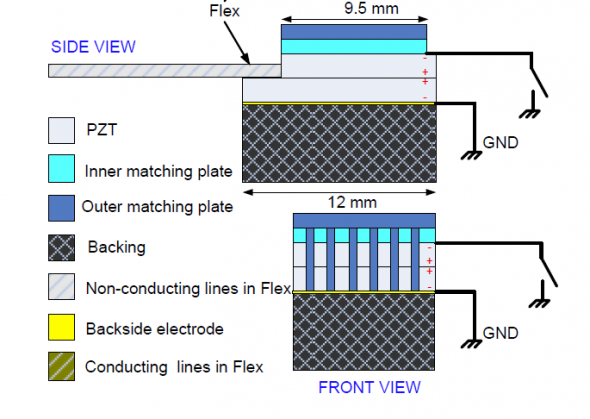
To excite the Lamb waves in the plate, an ultrasonic transducer with a centre frequency of 1 MHz and diameter of 25.4 mm was placed in the transducer and hydrophone holder array on top of the BeCaLoS, see figure 3. A needle hydrophone with diameter 0.5 mm was placed in a different holder to be able to detect the wavefront being radiated off the Lamb waves. In the following setup the upper layer is water, while the inside of the BeCaLoS representing the annulus, is filled with air.
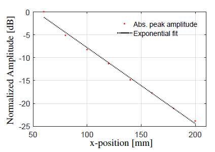
The transmitter and receiver was placed at different distances to each other, ranging from 60 to 200 mm along the propagation direction, to detect how the amplitude of the pressure wave generated by the Lamb waves decays as they propagate in the plate. The maximum amplitude of the pressure wave for various transmitter-to-receiver distances can be seen in figure 4, with an attenuation of 0.17 dB/mm originating from energy leaking into the water in contact with the plate. This attenuation number can give information about which materials are in contact with the plate, e.g. if water or cement where to be in contact with the lower side of the plate, a different attenuation number would be observed.
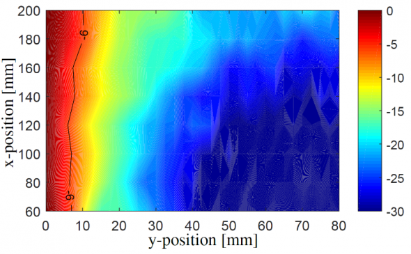
A paper on further experimental work conducted on the BeCaLoS together with a simulation study has been accepted as a conference proceeding at the International Conference on Offshore Mechanics and Arctic Engineering (OMAE) 2017.
Some more results can also be found in Acoustic measurements above a plate carrying Lamb waves by Talberg and Johansen.

Andreas Sørbrøden Talberg
Scientist, NDT Global, 2021-
Scientist, Halfwave, 2020-2021
PhD Candidate, CIUS, NTNU, 2016-
- Andreas Sørbrøden Talberg#molongui-disabled-link


